Welder Spool Gun Upgrade
|
|
|
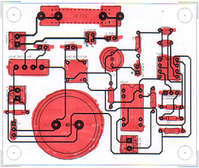
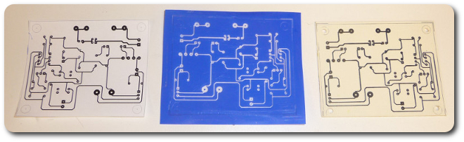
This printout is to scale (not here, of course) to make sure the real parts align with how the board will be made.
|
|
|
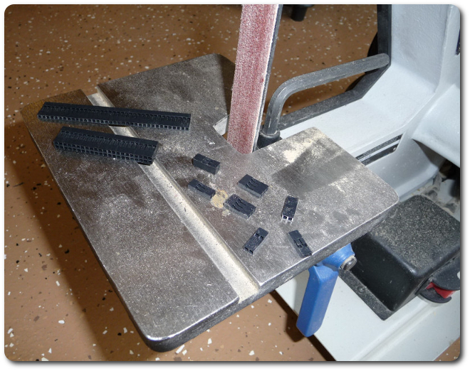
Some parts had to be modified. Instead of having every conceivable header strip, I buy the largest one (left), cut it on the bandsaw, and trim it here to whatever I need (right).
|
|
|
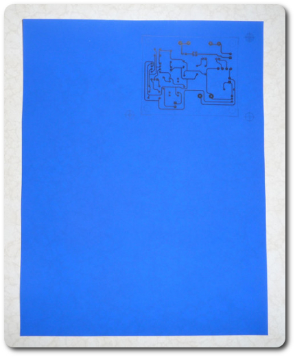
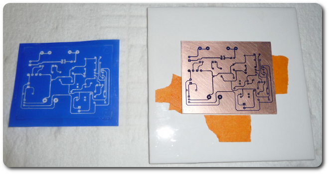
The circuit layout goes on the transfer paper. I have a fancier system now that uses a laminator, but parts of it weren't here due to my move. In any case, I've been using Press-n-Peel Blue forever, and I still love it. It's usually hit or miss on getting the temperature and pressure right for the transfer, which ends up requiring several tries, but today I got it right the first time.
|
|
|
|
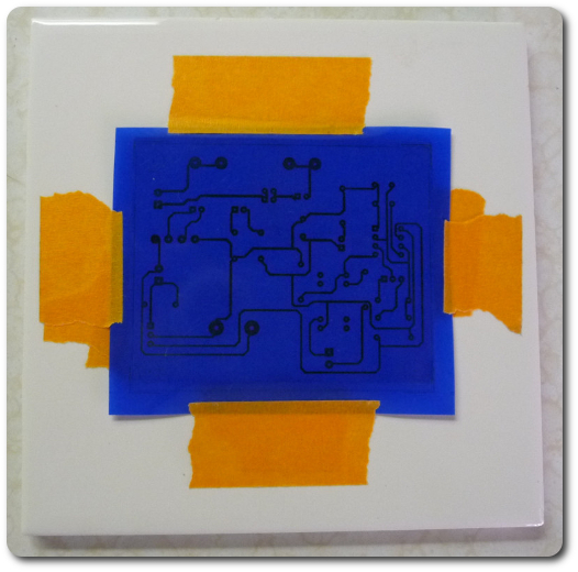
I don't have a picture of the ironing process, but this is the result. The iron is the background two pictures down. It's used to apply the plastic skin on model airplanes.
|
|
|
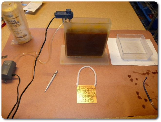
Normally I'd pull out my homemade etching tank with the heater and bubbler (here from the AquaDog project), but this is such a small, simple board, today it wasn't worth the effort.
|
|
|
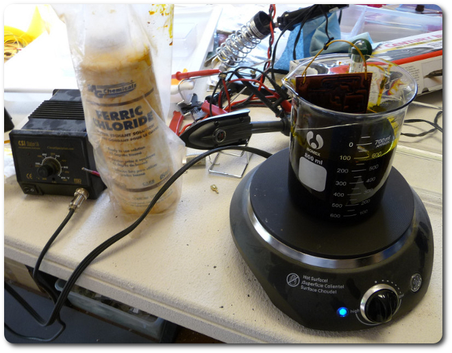
So I did it the straightforward way. And no, the hotplate is not from the kitchen.
|
|
|
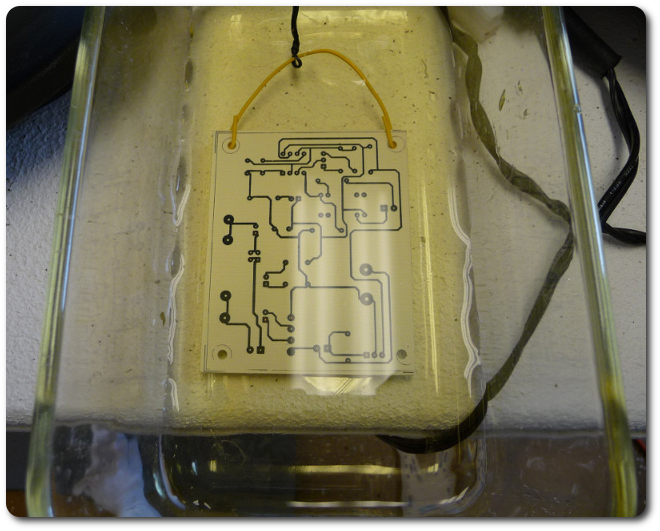
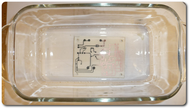
After etching, the board gets a quick bath in distilled water to wash off the ferric chloride.
|
|
|
And here's everybody: the paper proof copy, the spent transfer paper, and the etched board. The astute among you may notice that the board is a mirror image of the other two. That's not supposed to happen, but I hadn't made a board in a year, and I somehow I managed to select this option in Ultiboard. I was so excited about getting a perfect transfer on the first try that I didn't notice the error at this point.
|
|
|
An acetone bath removes the toner over the remaining copper.
|
|
|
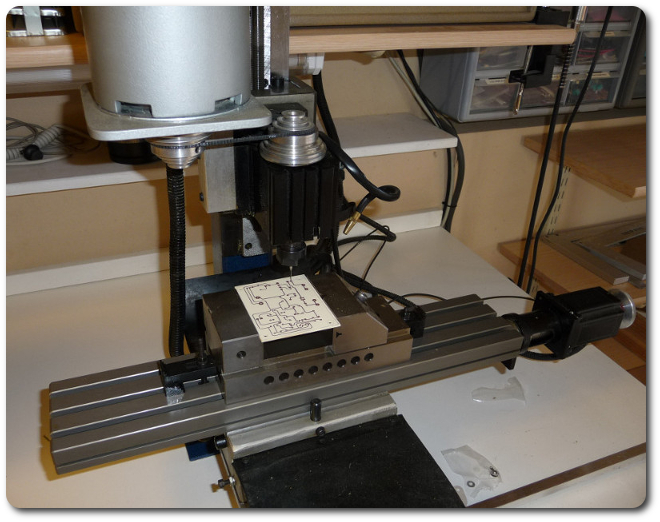
And now it's time to drill the holes. This is done manually on my mill, even though the hole positions could be exported as G-code from Ultiboard to Mach 3 for automatic drilling. The main issues here are the itty-bitty and very brittle bit (which I did not break) and any misalignment in the transfer. One bad hole can ruin the whole board, so I do this by hand.
|
|
|
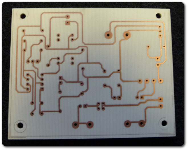
Pretty well, too. I always make the traces and pads extra large to account for any etching issues or small mistakes at this stage. I've never ruined a board in drilling. (I've ruined bits, though.).
|
|
|
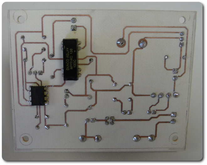
Not that I always get things right, though. Remember that mirror image above? Well, I managed to etch the board on the wrong side. For almost all the parts, this was irrelevant because they're symmetrical or don't have any particular orientation, so they stayed on the proper side. But the timer and relay are the exception, so they're on the bottom (top?) side now. For all practical purposes, this doesn't matter, but I couldn't use sockets because the legs aren't exposed for soldering.
|
|
|
Notice where the legs come up from underneath. Those two components should be on this side sticking through to the other.
|
|
|
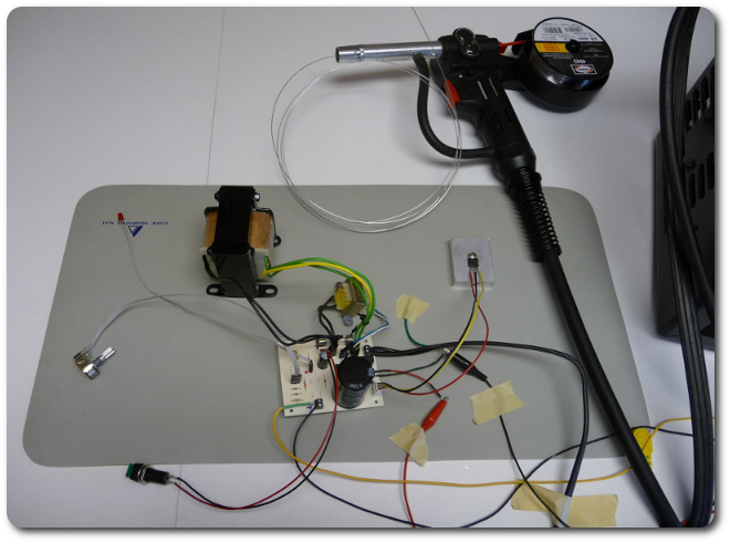
This is a test of the actual board before I start on its final form. Earlier the prototype on the breadboard drove the welder. Now it's the real circuit, with a little help from jumper wires and masking tape.
|
|
|
|
© 2026 Dan Tappan and Eastern Washington University
— last updated 27 May 2026 11:43