

|
|
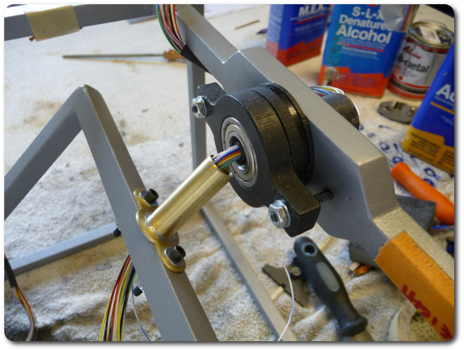
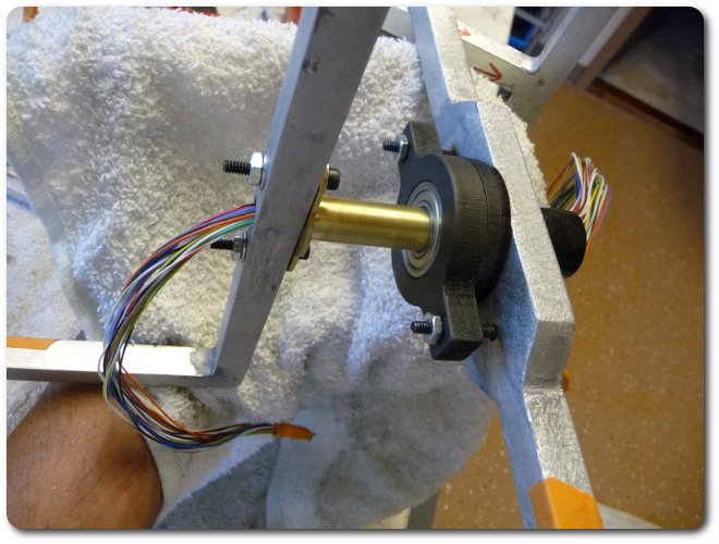
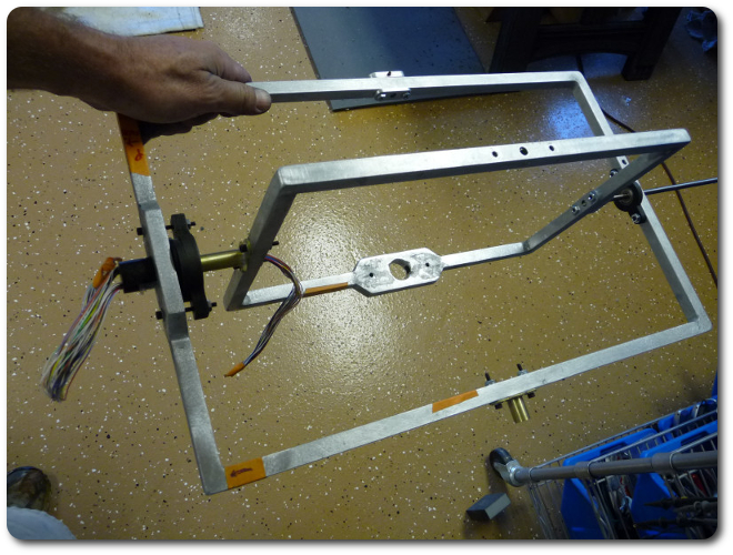
It's especially important to deburr the edges because these delicate wires are in close proximity to sharp, spinning surfaces.
|
|
|
|
|
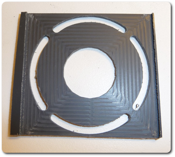
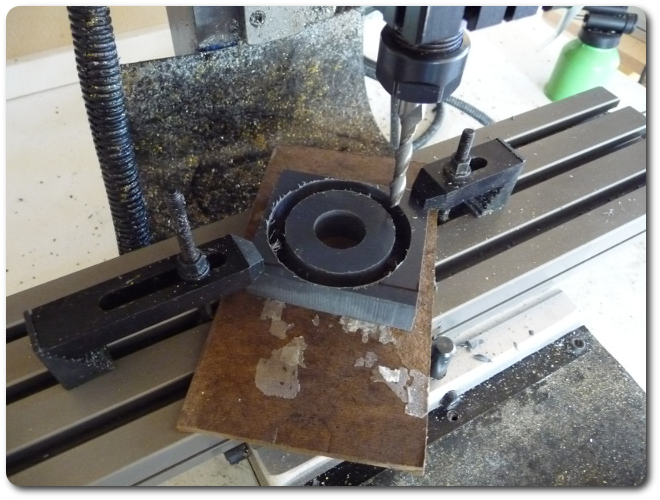
Here's what bridge tabs look like. This approach allows me to mount the stock from outside the cutting area, and the interior to be cut out stays as part of it due to the tabs. Note also that I had to face the PVC to be thinner for this spacer. It's small and hidden, so instead of face cutter, I ran a square cutting pattern with the same small end mill that cut the circle. This isn't efficient, but I didn't care. It also looks neat, although nobody will ever see this side.
|
|
|
Here's the same thing on a thick spacer.
|
|
|
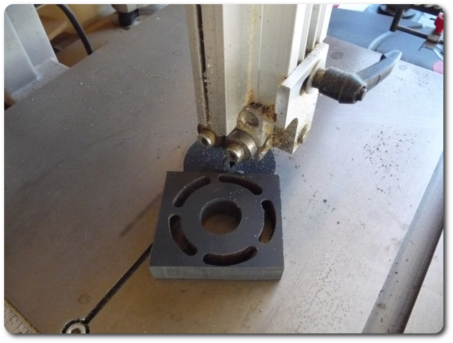
And here's what happens to those tabs.
|
|
|
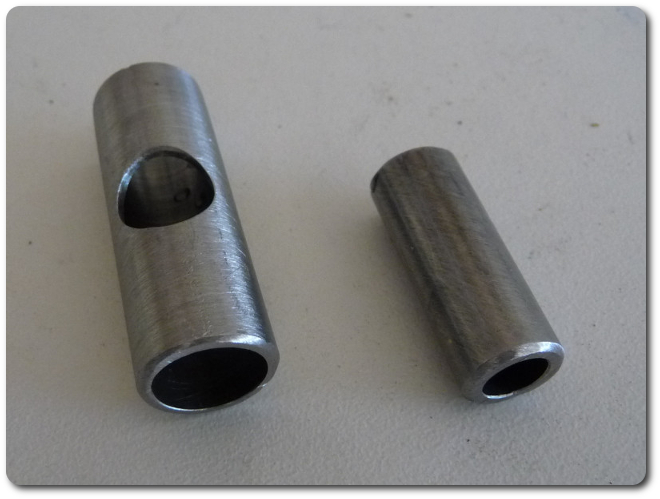
Now it's time for a thing of engineering beauty, in my opinion. (The brass flanged tubes are beautiful, too, but I was especially impressed with how this came out.) The yaw axis for the UAV resides in the innermost frame (of three) of the gimbal. It's a vertical shaft that goes through the top center. The rod needs to be narrow, but its mount end needs to fit the thick slip-ring bearing. And, as if this weren't enough, the mount needs to be hollow to allow the 24 wires to pass through and exit to the side. I had to build up the joint from smaller pieces of stainless-steel tubing.
|
|
|
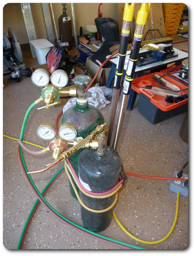
And now I get to have fun with oxyacetylene gas welding (technically brazing). Everything else has been MIG welded with 100% argon for shielding. But this assembly is just begging for brazing.
|
|
|
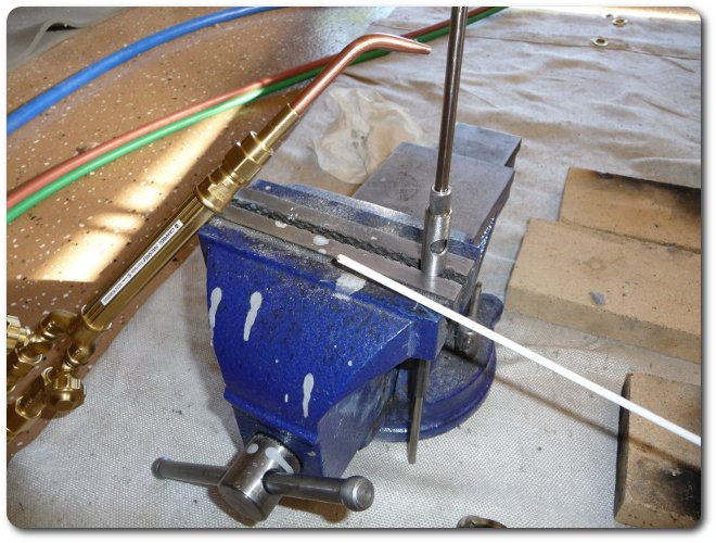
The shaft and telescoping tubes float freely with a little intentional space for the filler brass, which is on the white fluxed stick.
|
|
|
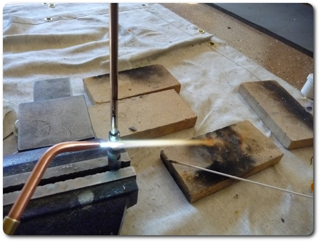
At 6,000°F, an oxyacetylene torch will melt anything on the planet, including the vise. But with a little care, I can direct a reduced flame at the assembly and have the brass melt nicely without affecting the steel at all.
|
|
|
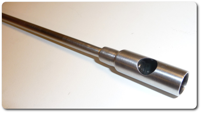
And here's what we get. Call me lame, but I think it's beautiful.
|
|
|
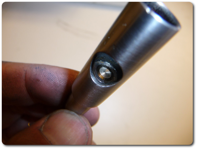
The great thing about this process is that the molten brass seeps into the joints evenly and keeps everything wonderfully in alignment.
|
|
|
Here's the entire shaft for the yaw axis. The set screw on the gear assembly would normally be aligned with the flatted section of the shaft to the right. Nobody ever sees the notch because the gear goes over it, but it still bugs me (ever the perfectionist) that I made it by hand and was a little crooked.
|

|
|
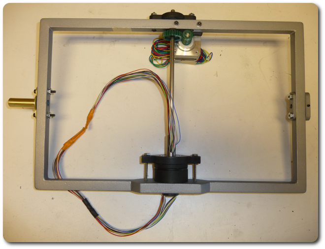
And here's it all put together.
|
|
|
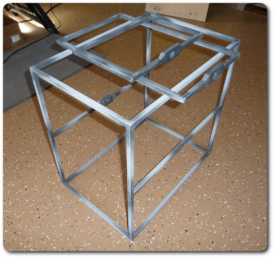
While all this was going on above (on Day 3), the primer on the frame was drying.
|
|


|