Three-Axis Electromechanical Flight-Simulation Gimbal
|
|
|
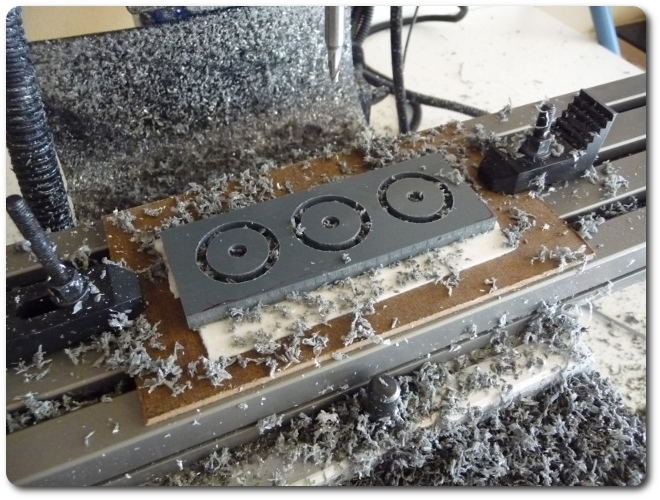
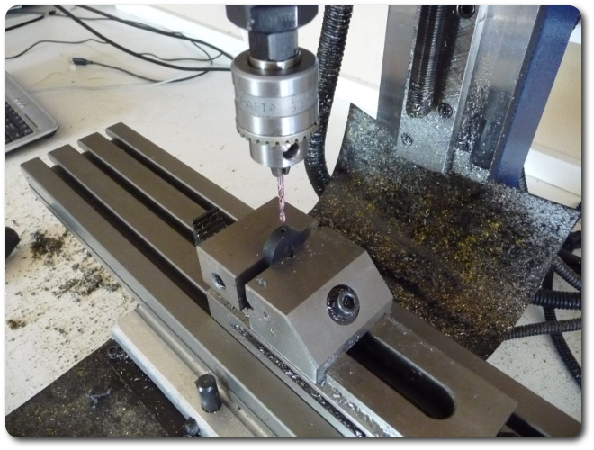
Despite having clamps and vises of every imaginable size, for little prismatic parts like these, double-sided foam tape is great.
|

|
|
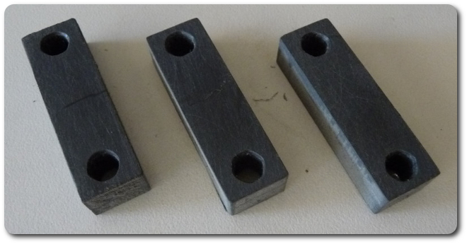
The holes on the stepper motors don't align with the frame, so again, a mount is necessary.
|

|

|
|
|
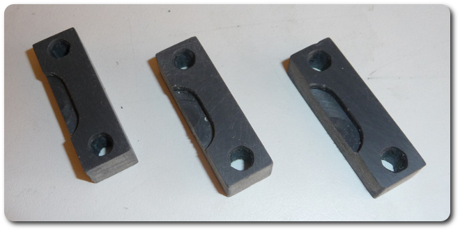
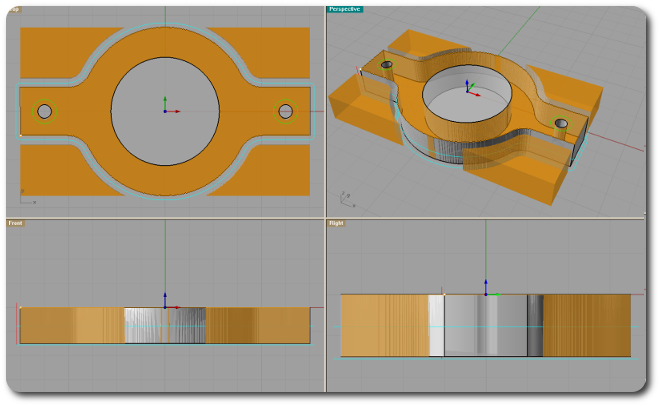
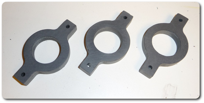
The cutouts accommodate the unused mount rings on the motors. These differ a little because they're cut manually. It doesn't matter because they're on the hidden side.
|
|
|
The pinion gears are also too thin to mount directly to the shafts, so they need some beefing up.
|
|
|
|
The gears take a relatively light load, which means the mount disk can be superglued.
|

|
|
But not before drilling and tapping a hole for a set screw.
|
|
|
The same goes for the shaft mounts. The bottom row secures differently with a screw longitudinally down the shaft, which explains why the mount is thinner and doesn't have a set screw.
|

|
|
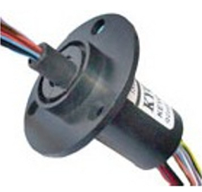
The slip rings (or rotary unions or couplers) transmit power and signals across the axes. Each has 24 wires. As we descend through each level of the gimbal's degrees of freedom, fewer wires are necessary, but for design simplicity, I used the same ones at each level.
|
|
|
Just as above, the slip rings don't align properly with the frame, and they need mount rings, too. Using the same slip ring for each level eliminates the need to design different mount rings.
|
|

|
|
|
But each level does require a different offset. On top the flanged base ring, which is the same for each level, I can adjust the depth with a spacer ring. This part of engineering design is something that's hard to get across to students. When we say the devil is in the details, we often mean it's the endless little realities of construction that pile on the time, complexity, and cost in a project. It's easy to abstract these bits away in the classroom, but they won't go away now.
|
|
|
|
© 2026 Dan Tappan and Eastern Washington University
— last updated 27 May 2026 11:43