Hard Drive Disk-Controller Demo

|
|
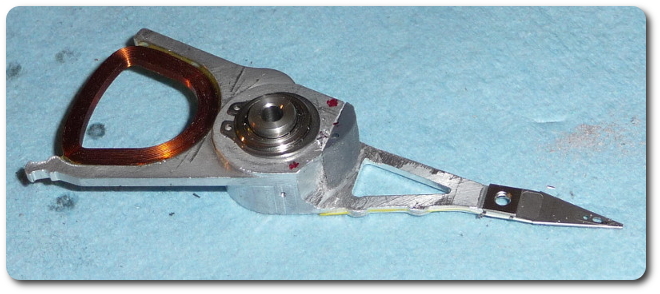
With all three stuck, there was no hope, so I added a plastic piece for the hole.
|
|
|
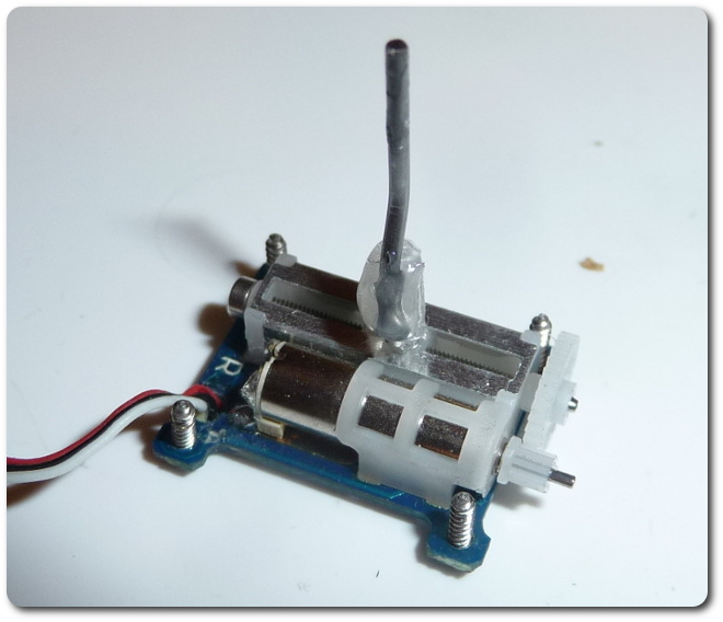
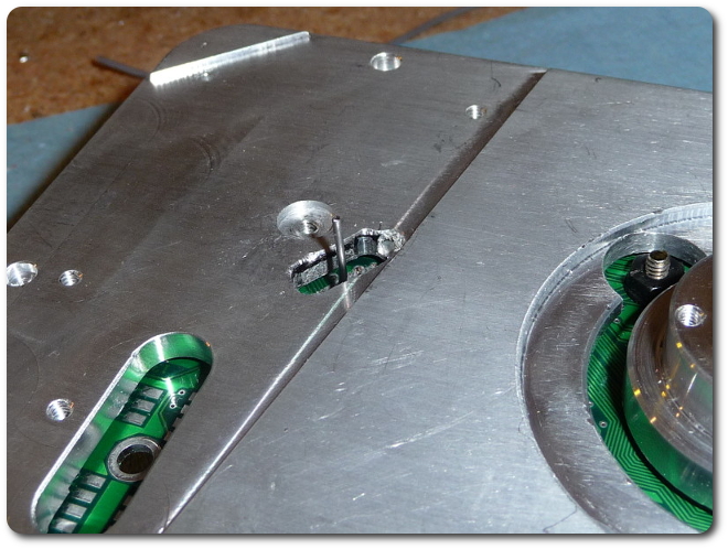
Here's the connecting pin. It had to be bent creatively because the hole didn't end up where it should have. Hot glue makes a great temporary mount.
|
|
|
|
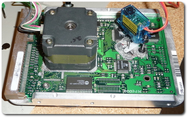
So after all that servo action, it turns out this approach wasn't acceptable. The linear servo didn't behave as well installed as it did free. Luckily the original design was for a standard rotary servo. All I needed to do was make some new holes and standoffs. And the connecting pin needed to be a little longer (although not quite this long; that's for ease of assembly).
|
|
|
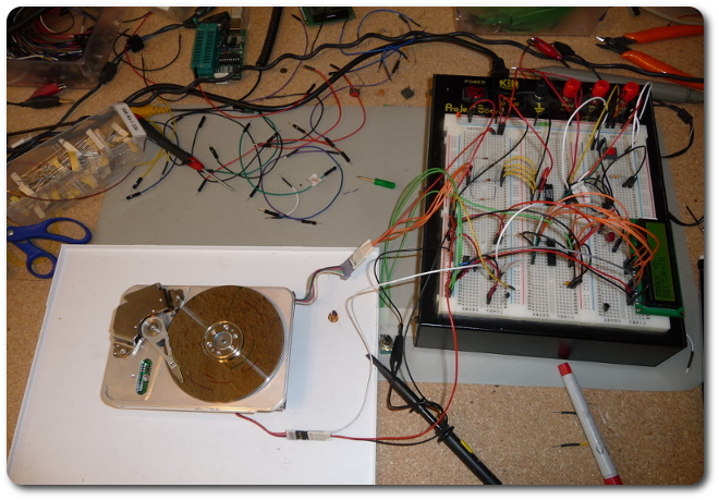
Here's the whole thing mostly ready to go. The main demo functionality is ready. What's missing is the auto-home feature to find the fake boot sector on power-up, and the read/write LED on the head. The LED is on the breadboard, though. Beyond that, it's etching a printed circuit board and fabricating an enclosure. This thing is definitely not portable, although I will be lugging it to class.
|
|
|
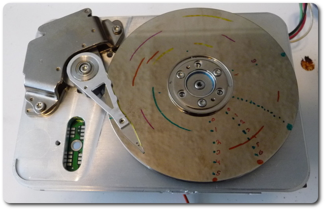
The calibration marks indicate my attempts at determining how many tracks and sectors to define. Obviously, capacity isn't the concern; it's making this interesting and informative. To this end, I went with six tracks and 20 sectors. the tracks are marked from center to 6 o'clock. The other marks are cluster tests. I'll wash all this off later and put in nice clusters.
|
|
This video is an example of it in action. The test isn't synchronized to the marks, but the basic idea is here.
|
(video 1 MB)
|
|
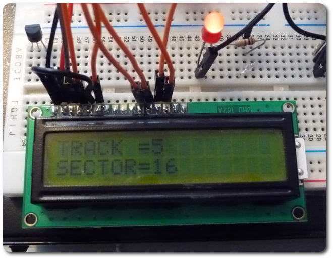
And a closeup of the display. The LED is the read/write indicator.
|
(video 2 MB)
|

|
© 2025 Dan Tappan and Eastern Washington University
— last updated 9 Apr 2025 15:44