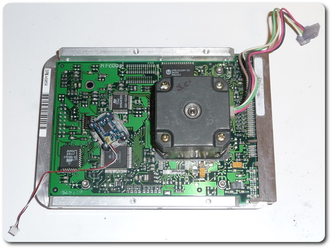
Hard Drive Disk-Controller Demo
|
|
|
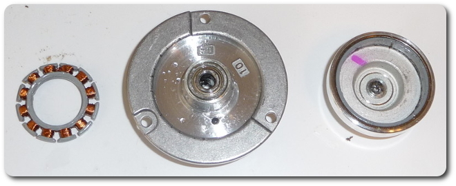
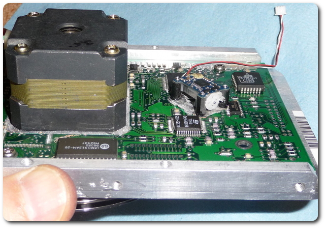
Then the motor itself had to come out because it causes self-induction when spun by my stepper motor, and this makes the rotation less smooth.
|
|
|
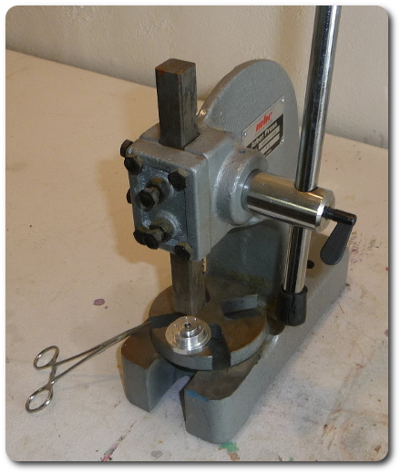
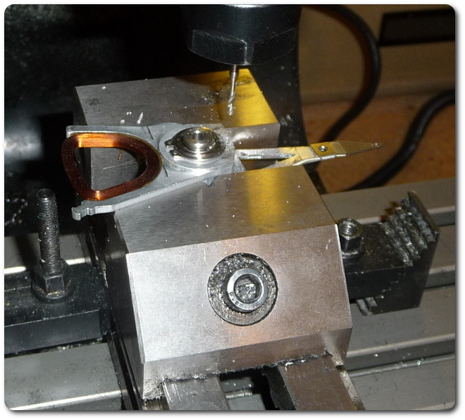
And finally the bearing had to go. This involved an arbor press and a ball bearing to focus the force (and a hemostat to hold the ball bearing, which didn't actually work the first time — it's out there somewhere).
|
|
|
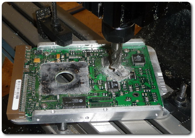
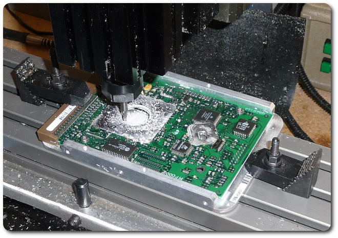
Now it was time to make mount pads for the stepper motor and servo assembly. I felt like a tornado cutting through a trailer park as these little chips and things got in the path of this huge end mill.
|
|
|
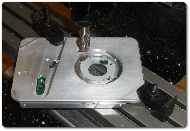
The original hole needed to match the mount ring on the stepper motor.
|
|
|
And the original screw holes didn't align, of course.
|
|
|
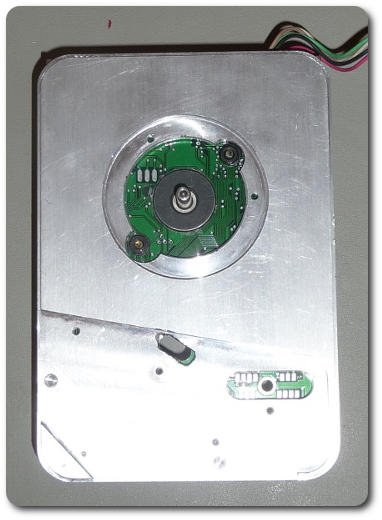
At this point, it looks like this, with the stepper motor firmly attached.
|
|
|
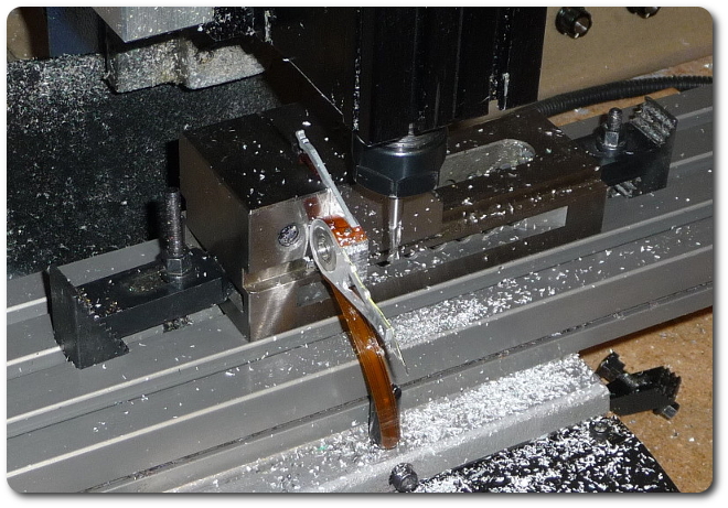
The arm of the read/write head needed some rocket surgery. Only the top head is being used because it's the only one visible, so the others were eliminated.
|
|
|
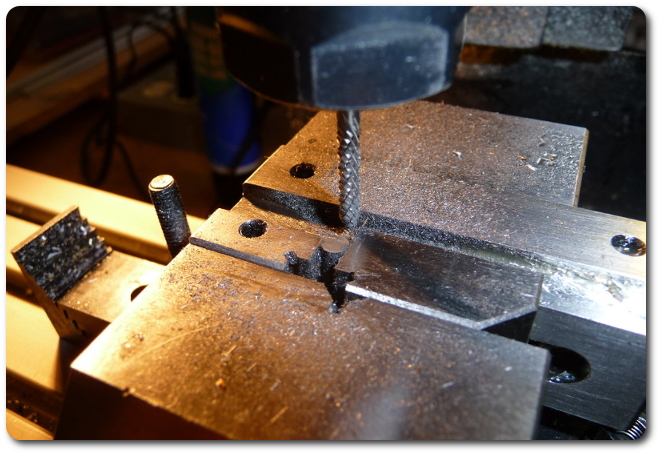
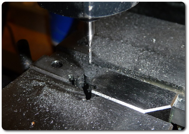
Now it's time to make standoff posts for the little servo that drives the arm. It's not designed to be mounted upside down, so I had to get creative. Here's trimming down 1/4" fiberglass rod to about 3/8" long. It's a carbide bit because fiberglass is rough on high-speed steel. This is the "vise in a vise" trick, where the little guy is sideways so the process is repeatable across all four standoffs.
|
|
|
|
And there needs to be a hole for the mounting screw.
|
|
|
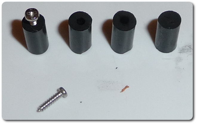
All four ended up like this.
|
|
|
And they attach this way.
|
|
|
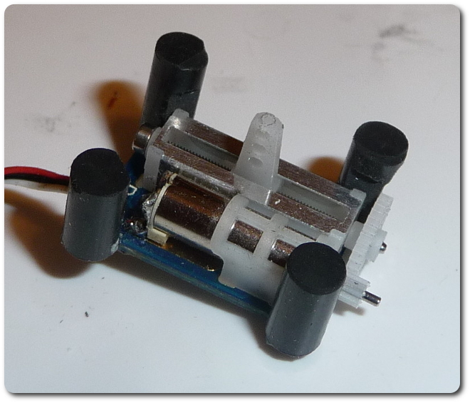
The servo can now be mounted quite nicely.
|
|
|
|
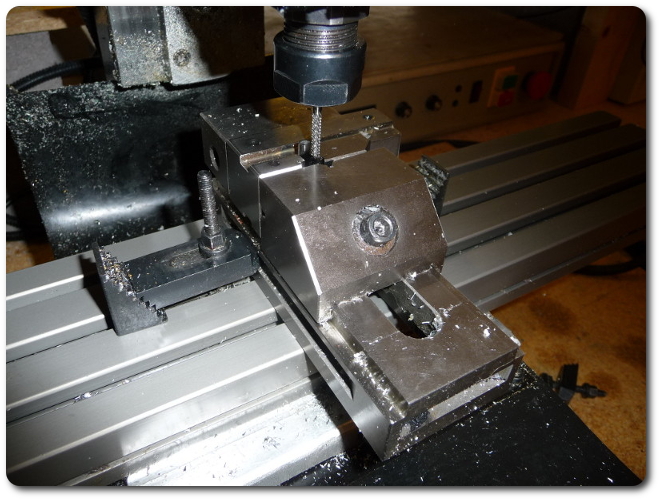
The head assembly needed a small hole for the drive shaft. I broke three bits doing this. Not only is that a waste, but they each got stuck in the assembly, which meant I had to drill the next one slightly off target.
|
|
|
|
© 2026 Dan Tappan and Eastern Washington University
— last updated 27 May 2026 11:43