Welder Power Adapter
|
|
|
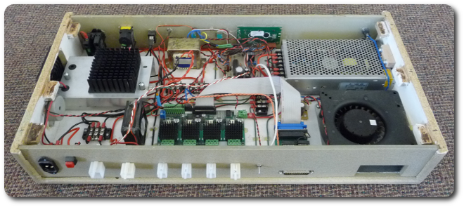
On the back side, there's a red push button for fan speed (normally low) and a toggle switch to engage the fourth-axis rotary table, which is not normally connected.
|
|
|
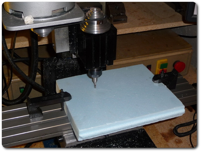
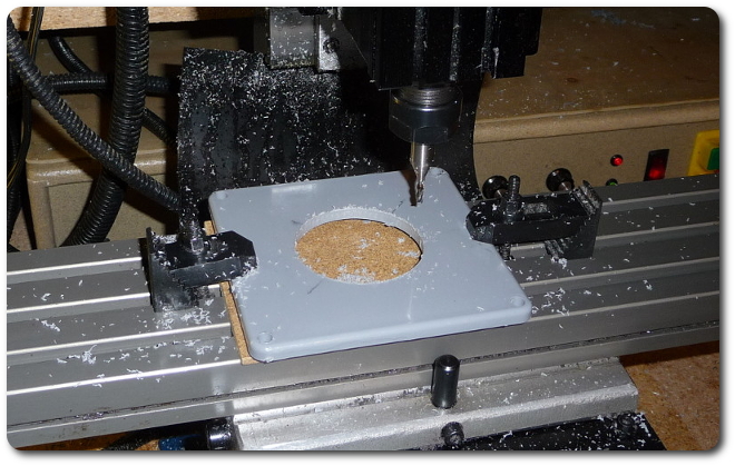
After all this, the end mill is centered. Of course, this blue piece of foam isn't the actual work piece. Especially since I'm photodocumenting this project, I want to cut a test piece to be sure I don't screw something up. (Did I mention already that I don't trust myself?).
|
|
|
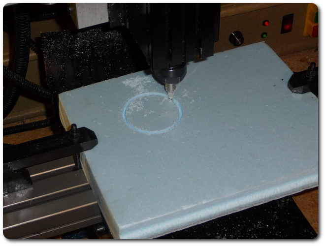
And here's the result -- no screwups.
|
|
|
And here's a video of the real thing. The PVC swarfs up badly, which makes the cut hard to see, but it deburrs right off for a clean edge later.
|
(video 4 MB)
|
|
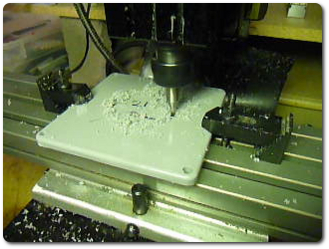
And the result.
|
|
|
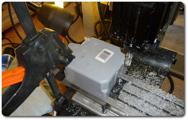
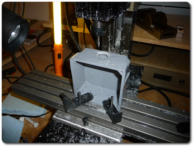
Now for a little bit of work on the back side to cut off the flanges. There's no convenient way to mount this box. Bar clamps are definitely not the norm!.
|
|
|
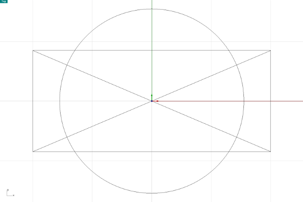
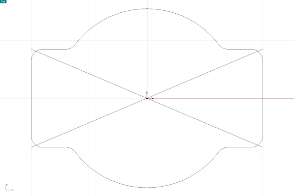
Next up is to cut the entry hole for the power cables. This box accommodates two: one flat for the NEMA 10-30/10-50 cable, and one round for the 14-30/14-50 cable. The first step of the machining process is the rough layout using a rectangle, circle, and two diagonal lines to mark the center.
|
|
|
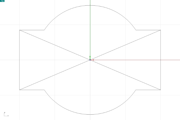
Then the non-cut segments are deleted.
|
|
|
And finally the corners are radiused so they're not sharp.
|
|
|
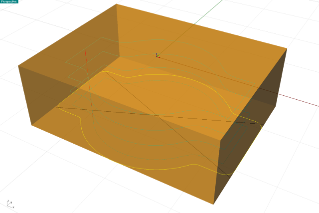
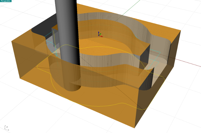
And here's the cut rendering.
|
|
|
|
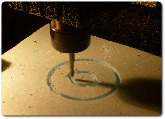
And a test cut, of course. The center point from the previous test was convenient to reuse.
|
|
|
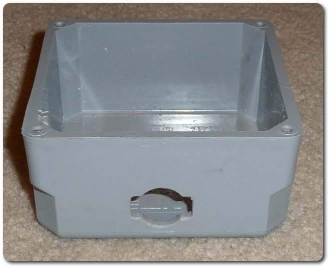
And now the real thing.
|
|
|
So far, so good.
|
|
|
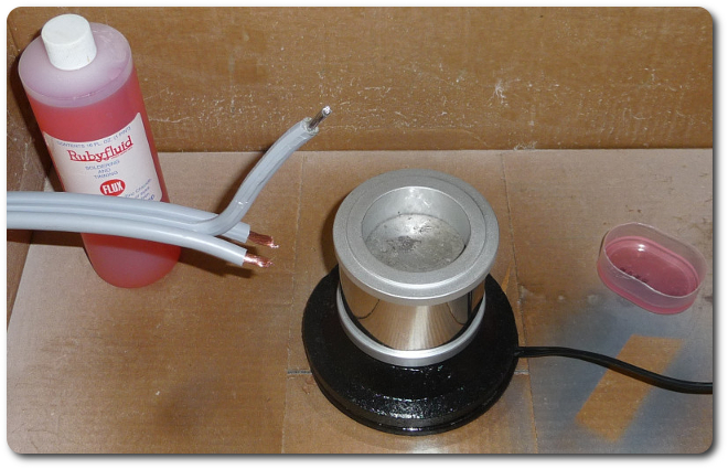
Now over to the electrical world. Each of the two cables has thick wires (either three or four) that plug into the 10-50R receptacle in the box. Since this adapter is meant to allow them to be interchanged relatively easily, the ends of the wires need to be tinned well. For something this thick, a soldering iron won't work, and a mini-torch is a little too indescriminate in its heat transfer. The solder pot is ideal. But pure solder doesn't have a flux, so each end first goes into zinc chloride, then into the pot for a quick swim.
|
|
|
|
© 2026 Dan Tappan and Eastern Washington University
— last updated 27 May 2026 11:43