Welder Power Adapter
|
|
|
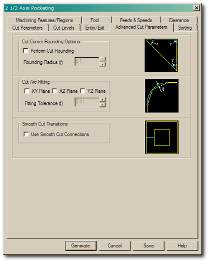
The advanced settings are to use bridged tabs (or sprues), which keep the inner piece connected to the outer piece with small tabs that aren't cut out. There's no actual option for this here because, ah, I took screenshots of the wrong process. This is pocketing, which would cut the entire center hole out. In reality, I want profiling, which cuts only the arc.
|
|
Tabs aren't strictly necessary here. Normally it's the inner part that should be saved, and the outer part is waste. In that case, something needs to hold the inner part to the outer while it's being cut out. But in the opposite case here, the outer part isn't going anywhere (it's clamped). The tabs do keep the inner part behaved, though, because it may decide to depart on its own toward the end.
|
|
|
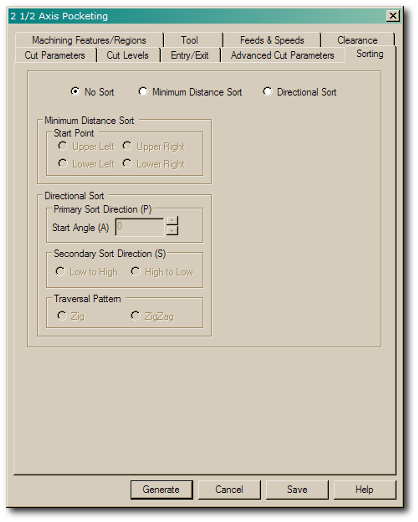
And finally there's sorting, which makes no sense when there's only one cut path. But if there were multiple paths, this would allow finer control over the order.
|
|
|
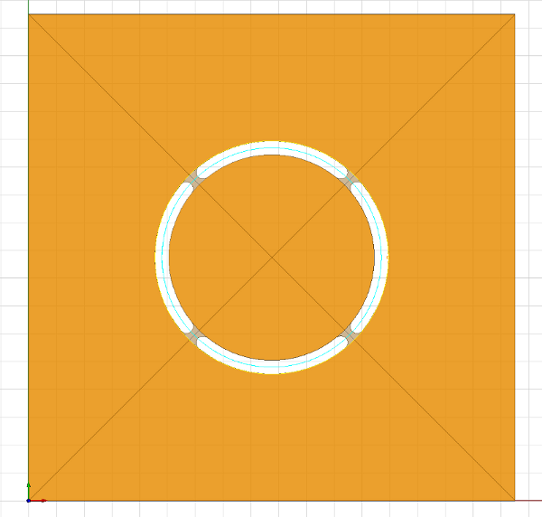
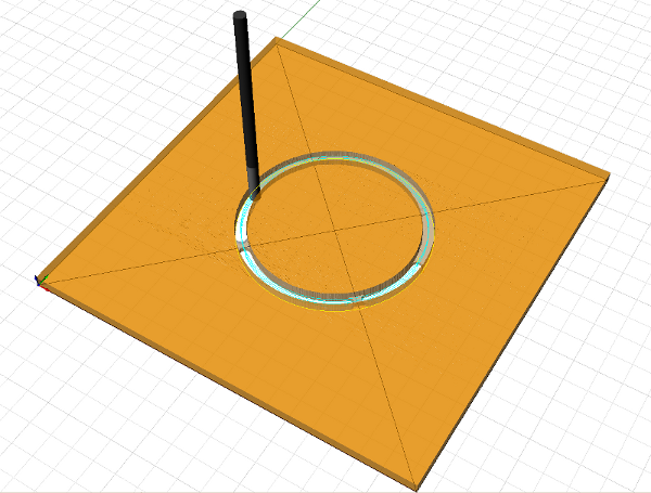
Here's what the cutout looks like, including the bridged tabs.
|
|
|
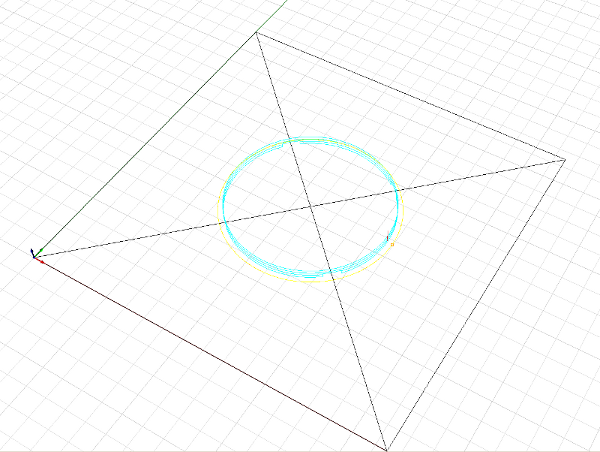
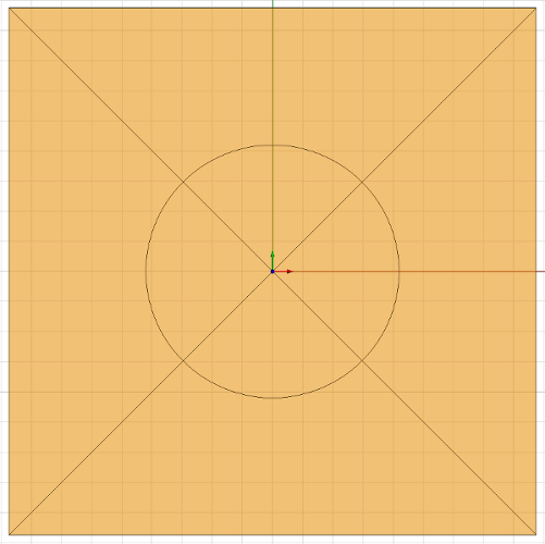
And without the stock in the way. The cyan lines are the cut path.
|
|
|
This video shows how it will be cut.
|
(video 3 MB)
|
|
One modification is necessary. The origin (red, green, and blue arrows) of the work piece is currently at the bottom-left corner (which makes sense during the CAD layout because all measurements are positive). Since this circle has a nicely defined center, though, it makes more sense to use it for the origin on the actual cut. This way I can position the end mill right over the X on the work piece without having to measure relative to the corner (which would be dicey because it's not a sharp corner on the actual PVC piece).
|
|
|
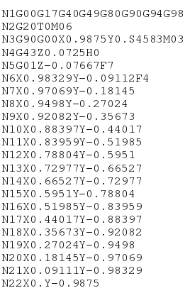
The G-code generated from this process goes on for about 220 lines. It's all line segments approximating a circle, nothing fancy. People can read and write this stuff by hand, but for an automated system like mine, I don't normally look at it.
|
|
|
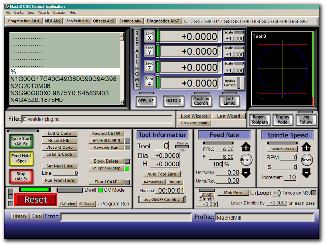
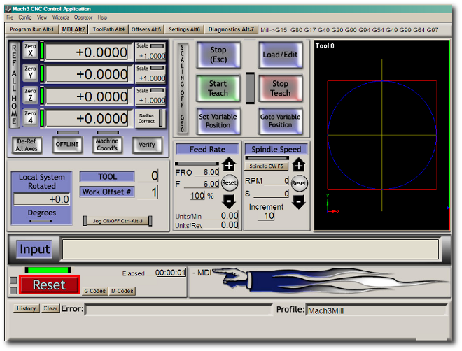
Now it's time to load the G-code into Mach3 on the computer that drives the mill. The x, y, and z positions need to zeroed out. This is a common (dumb) omission on my part, which makes the controller think it's somewhere else on the work piece when it starts.
|
|
|
Instead of hand-cranking over major distances to rough-position the work piece, I enter manual G-code for fast transits here.
|
|
|
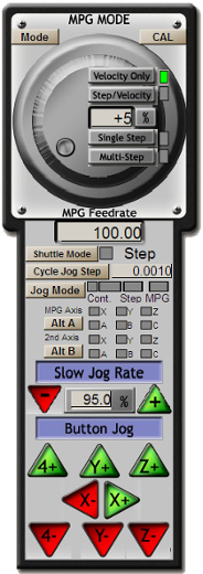
Then for intermediate positioning, the GUI version of a pendant (another pending project is to make a real one) allows clicking instead of cranking.
|
|
|
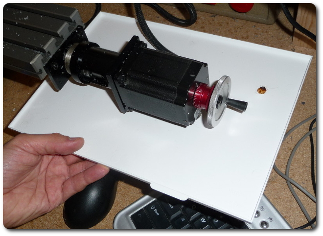
Then to fine-position, I use the hand cranks. The combination of manual and computer-controlled modes is invaluable. Normally manual cranking is a non-precision process when I don't care about appearance, but it can be precise. Each of the four cranks (x, y, and z axes for the mill and a axis for the rotary table) has a rotating, locking scale ring. Twenty rotations is an inch of linear travel, and one rotation is five degrees on the rotary table.
|
|
|
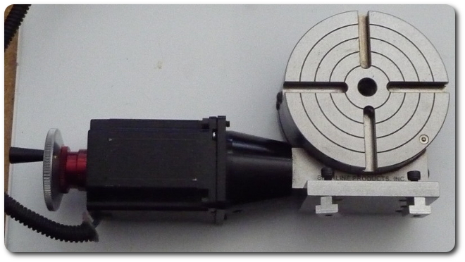
The rotary table.
|
|
|
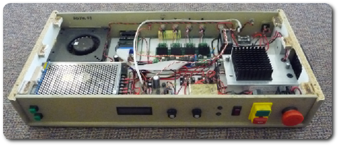
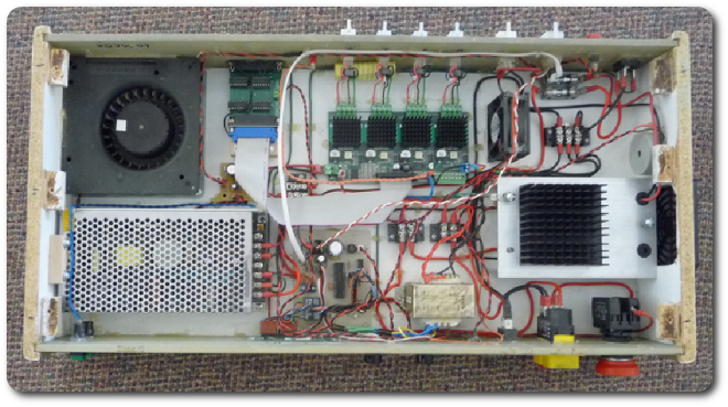
Mach3 feeds the controller I built to drive a Xylotex stepper-motor controller (toward the top center, with the four black heatsink squares). The interface corresponds left to right to: buttons for manual/auto mode (for hand cranking); the display for bit diameter, spindle speed, and surface feet per minute; the knobs for bit diameter and spindle speed, the indicator lights for master power and cutting-motor power; the master power switch; the safety-interlock switch to engage the cutting motor; and the emergency stop mushroom.
|
|
|
|
|
© 2026 Dan Tappan and Eastern Washington University
— last updated 27 May 2026 11:43